terminal descent & landing
As was briefly discussed in the Mission Sequence of Events, Terminal Descent occurs after the final firing and subsequent jettisoning of the PSAM.Terminal descent consists of two phases. The first phase is an unpowered coasting phase where the lander simply loses altitude. The second phase is a powered descent phase utilizing a monopropellant hydrazine descent engine and a gravity turn terminal descent guidance algorithm. The entire terminal descent phase is simulated using a MATLAB code called trajsim.m. This code uses numerical integration to simulate both the coast phase and the powered terminal descent phase. Upon completing the landing simulation, the code outputs the following data and plots relating to the terminal descent.
-------------------------------------------------
LUNAR TERMINAL LANDING SIMULATION
-------------------------------------------------
Initial State Data
-------------------------------------------------
Dry Mass 67.692 kg
Fuel Mass 47.5 kg
Total Entry Mass 115.192 kg
Orbital Radius 100 km
Rel Orbital Velocity 1.68475 km/s
Deorbit Delta-V -0.685 km/s
Ballistic Velocity 0.999747 km/s
Terminal Thrust Avail 400 N
-------------------------------------------------
Conditions at Start of Gravity Turn
-------------------------------------------------
Velocity 1.04259 km/s
Altitude 69.9189 km
FPA -12.8727 deg
Slant Range 313.84 km
Thrust 386.097 N
-------------------------------------------------
Gravity Turn Summary Data
-------------------------------------------------
Grav turn duration 321.1 sec
Total entry time 581.1 sec
Grav turn dist 148.218 km
Total entry dist 409.583 km
Final FPA -88.9205 deg
Propellant mass used 47.4631 kg
-------------------------------------------------
***NOTE: You have excess terminal descent fuel!***
-------------------------------------------------
Trajsim.m output
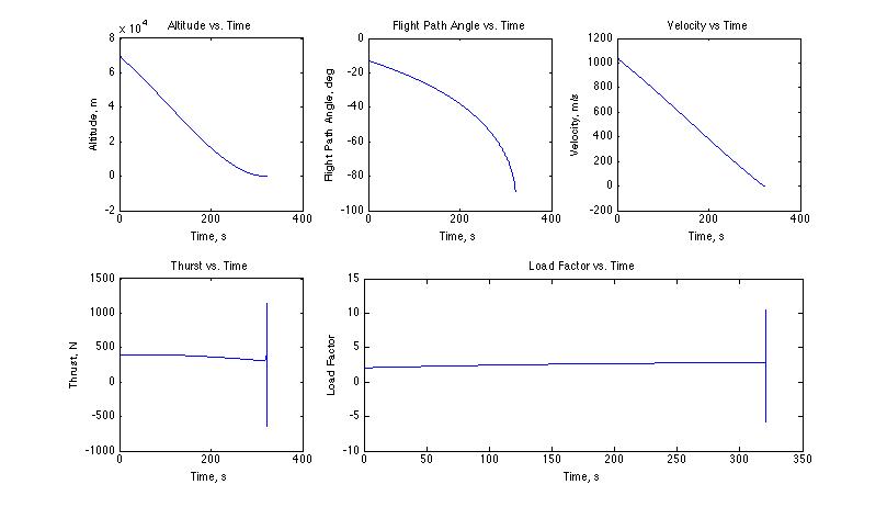
Gravity Turn Performance Plots
Summary: Coast Phase
Following the deorbit burn, Googol enters into the unpowered coast phase. Examining the MATLAB output, Googol begins this phase with a ground-relative velocity of approximately 1 km/s and travels 261.365 km (ground track) over a period of 4.3 minutes. Since the Moon has no atmosphere, Googol’s velocity is actually increasing during this phase unlike on Earth or Mars, where a vehicle slows while passing through the atmosphere. The coast phase is NOT displayed in the plots above.
Summary: Gravity Turn Phase
As indicated in the MATLAB output, the gravity turn begins at an altitude of 70 km above the lunar surface when the Googol has a ground-relative velocity of 1.04 km/s. The gravity turn lasts for 5.35 minutes and takes place over 148.218 km.
Examining the gravity turn performance plots above, one can see that the lander enters the gravity turn at a very shallow flight path angle, but the guidance algorithm is able to bring slow it to zero velocity at the lunar surface with a -90° flight path angle (i.e. Googol lands vertically). During the course of the gravity turn, the hydrazine descent engine maintains near-constant thrust near its maximum thrust level of 400 N. Furthermore, the lander maintains a relatively low load factor between 2 and 3 g’s during descent and landing. The spikes in the thrust and load factor plots should be ignored, as they are simply artifacts of numerical integration. As one can see from the MATLAB output, the lander carried precisely the amount of descent fuel it required so as to not add any unnecessary weight.
Gravity Turn Terminal Guidance Explained In-Depth
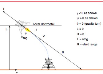
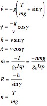
The above diagram and equations of motion characterize the gravity turn problem. For this mission, the Googol lander implements a guidance law similar to what was used by the Lunar Surveyor landers. The guidance law is as follows:
![]()
An interesting point to note is that this guidance law assumes a relatively small initial nadir angle. Although that is not the case in this scenario, this guidance law still performs acceptably.
In the simulation, it is assumed that the R and v calculated from the equations of motion are what the lander is actually experiencing. In reality, R and v are measured from radar and/or accelerometers, which allows the thrust to be calculated. Then the measured load factor measured from an accelerometer is used to close the control loop. That is, the error being minimized is the difference between the measured load factor and the calculated load factor.